PLC Logic Functions Instrumentation Tools
Last Updated on: April 29, 2020 by Rick Phillips How do you program a PLC? PLC Programming starts by identifying the problem, creating a sequence of operations based on binary logic, entering a program using a language, and simulating the program in your software.
PLC Basics Ladder Logic Common Functions Owlcation
Programmable Logic Controllers (PLCs) form their backbone, allowing internal components to function together as a seamless unit. Versatile and modifiable, these digital computers are essential to many of the systems and devices we rely on today.
PLC Functional Block Diagram basics YouTube
Ladder logic is a staple of PLC programming, and it is, more often than not, the most used language in a PLC program. It's used because it's easy to read, easy to use, and lends itself to logical processes, especially where digital logic (relay logic) is concerned.
PLC Logic Functions Instrumentation Tools
An Introduction to Programmable Logic Controllers March 10, 2022 by Stephen St. Michael What is a PLC? This article will lay out a succinct definition of a programmable logic controller and explain its basic components. The programmable logic controller, or PLC, is ubiquitous in every kind of process and manufacturing industry today.
PLC Basics Ladder Logic Common Functions Owlcation
The PLC uses logic to decide how the outputs will be set. The inputs of all this logic will represent the PLC inputs. All the logic will be our PLC program. At last, the outputs of the logic will be the outputs of our PLC program. Your First PLC Logic Program Now, let us get started by making a very simple imaginary PLC program with PLC logic.

PLC Logic Functions PLC Ladder Logic Gates PLC Commands
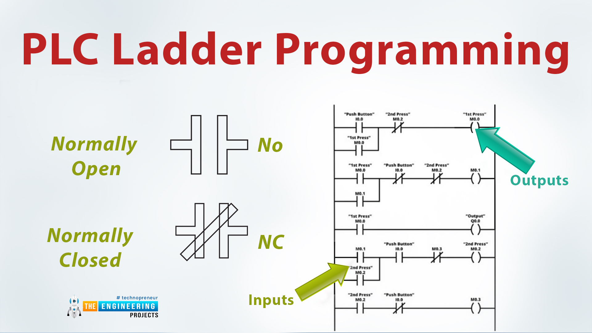
Ladder logic is a programming language that is used to program a PLC (Programmable Logic Controller). It is a graphical PLC programming language which expresses logic operations with symbolic notation using ladder diagrams, much like the rails and rungs of a traditional relay logic circuit.
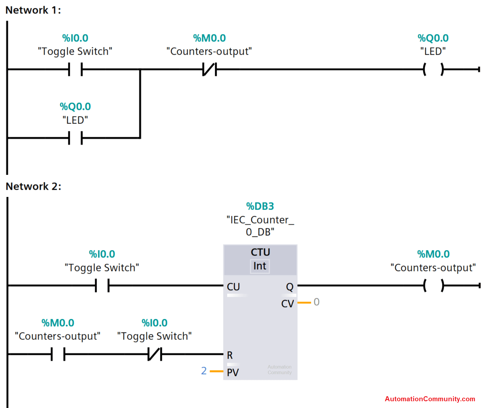
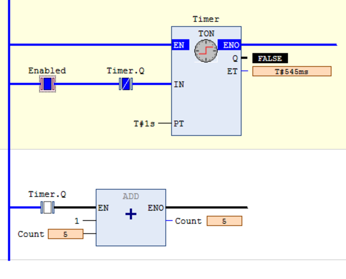
Toggle Switch in PLC Ladder Logic using Counter
The purpose of a PLC was to directly replace electromechanical relays as logic elements, substituting instead a solid-state digital computer with a stored program, able to emulate the interconnection of many relays to perform certain logical tasks. Ladder Logic and Programming PLCs
Logic Ladder Diagram Examples / Examples Of Plc Ladder Logic Diagrams Ladder Logic Logic Plc
Ladder logic (also known as ladder diagram or LD) is a programming language used to program a PLC (Programmable Logic Controller). It is a graphical PLC programming language which expresses logic operations with symbolic notation. Ladder logic is made out of rungs of logic, forming what looks like a ladder - hence the name 'Ladder Logic'.
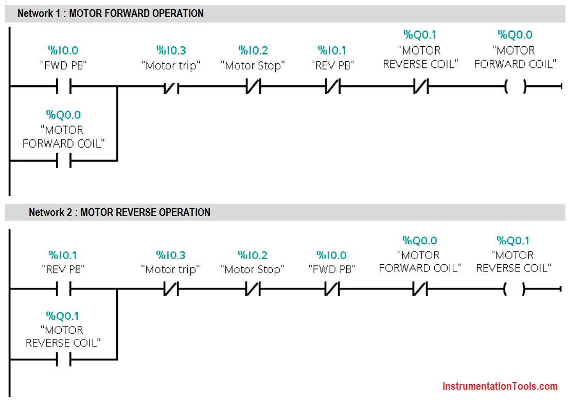
3 Phase Motor Control using PLC Ladder Logic PLC Tutorials Point
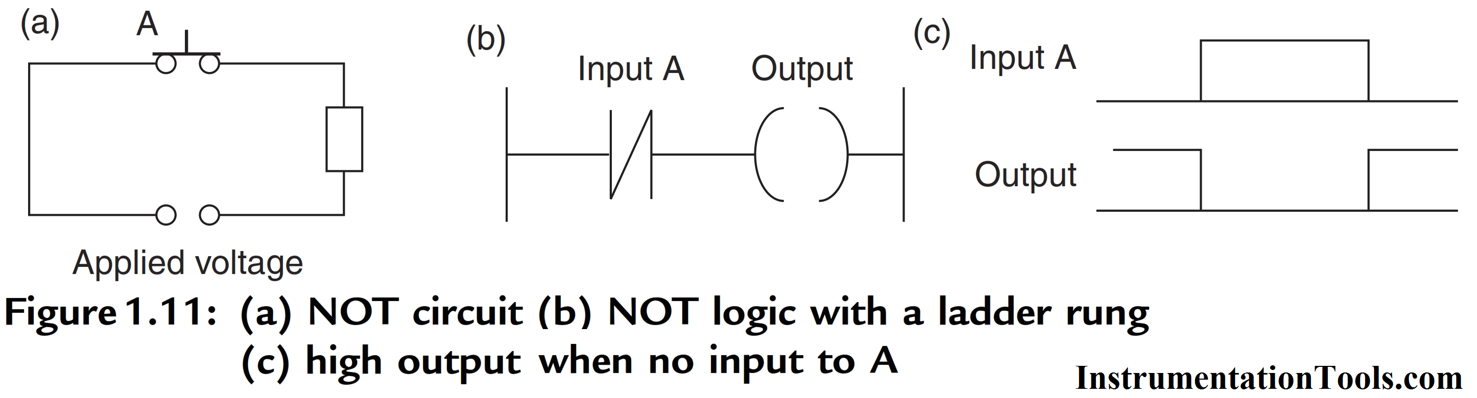
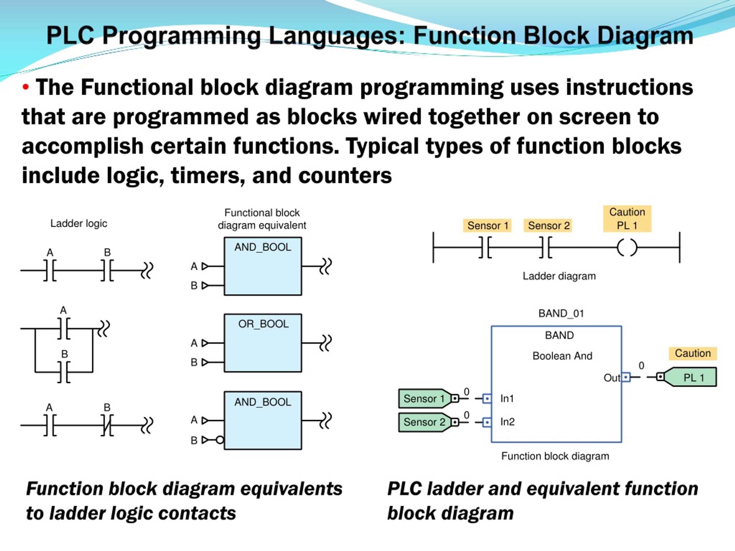
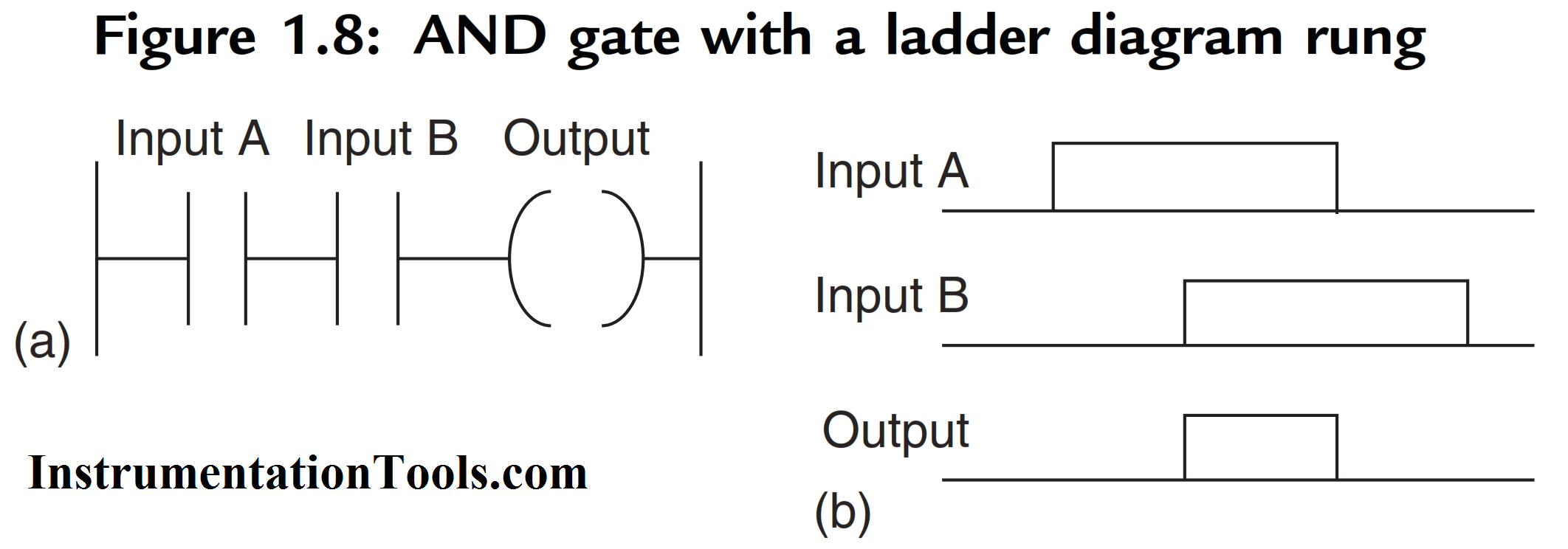
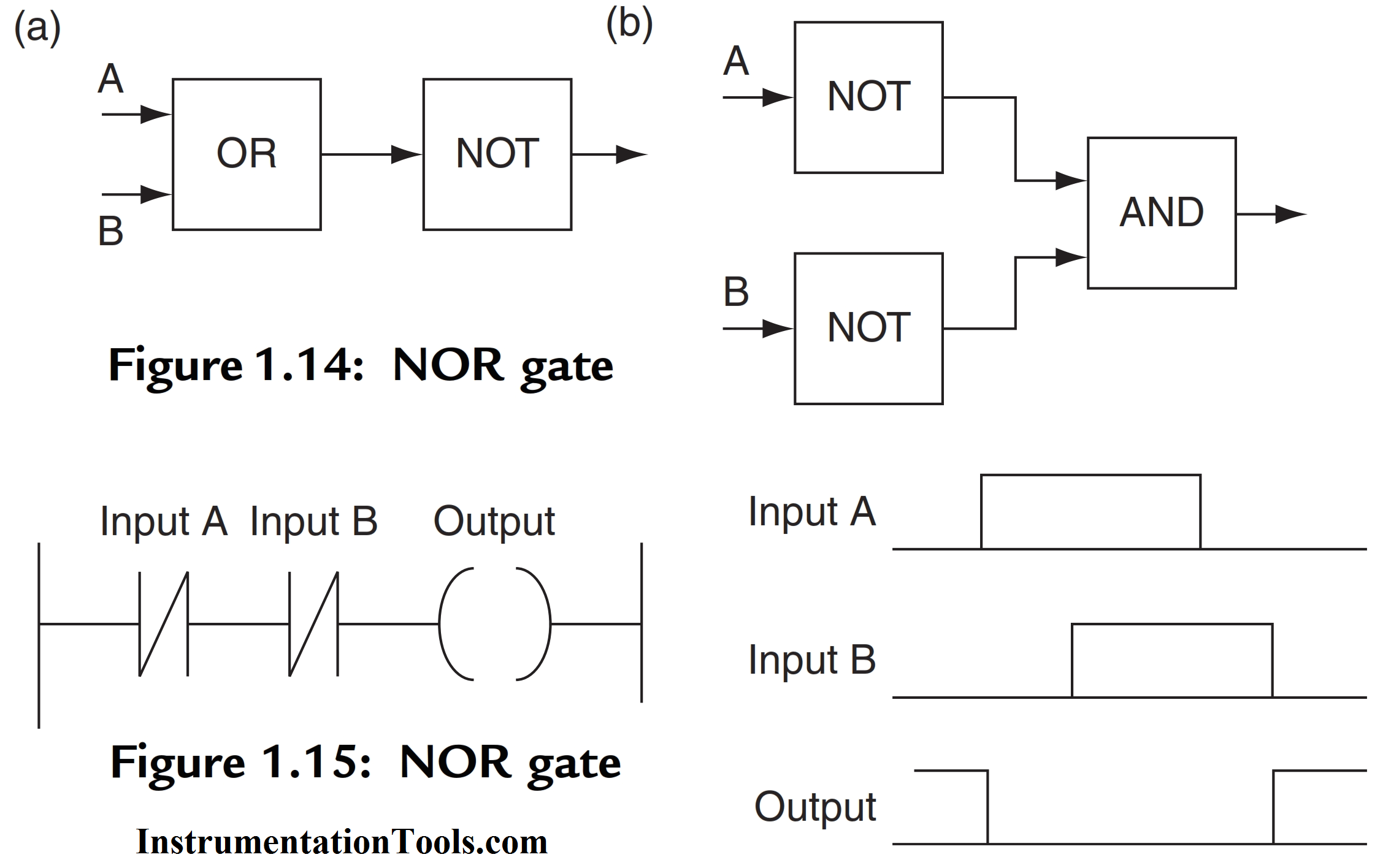
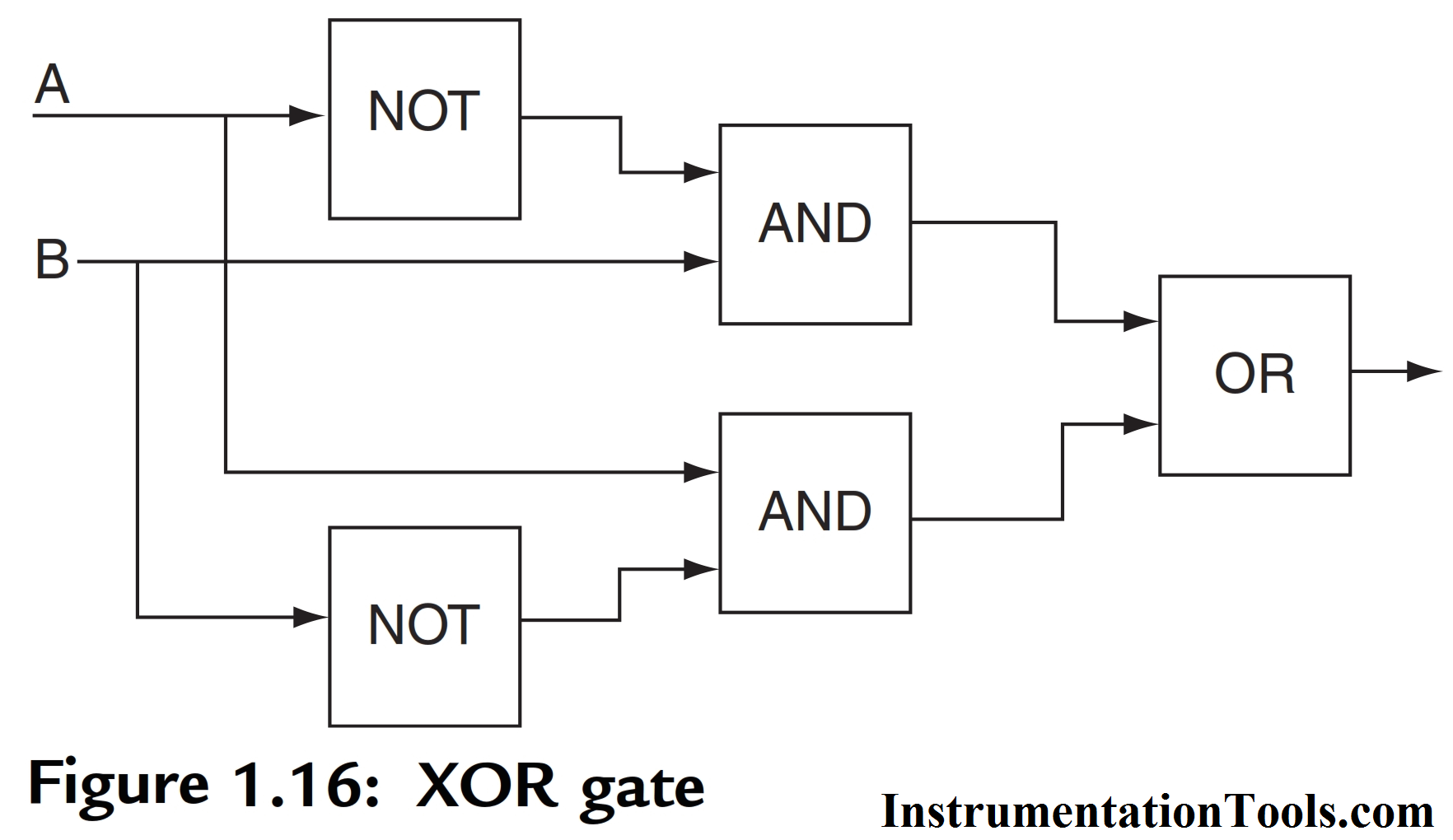
In general: On a ladder diagram contacts in a horizontal rung, i.e., contacts in series, represent the logical AND operations. PLC OR LOGIC Figure 1.9a shows an electrical circuit where an output is energized when switch A or B, both normally open, are closed.

How the PLC Revolutionized Industrial Process Control Engineering360
As computers, PLCs can perform timing functions (for the equivalent of time-delay relays), drum sequencing, and other advanced functions with far greater accuracy and reliability than what is possible using electromechanical logic devices. Most PLCs have the capacity for far more than six inputs and six outputs.
PPT Basics of PLC Programming PowerPoint Presentation, free download ID403466
ADVANCED LADDER LOGIC FUNCTIONS Topics: Shift registers, stacks and sequencers Program control; branching, looping, subroutines, temporary ends and one shots Interrupts; timed, fault and input driven Immediate inputs and outputs Block transfer Conversion of State diagrams using program subroutines Design examples Objectives:
PLC Logic Functions Instrumentation Tools
PLC stands for "Programmable Logic Controller". A PLC is a computer specially designed to operate reliably under harsh industrial environments - such as extreme temperatures and wet, dry, and/or dusty conditions. PLCs are used to automate industrial processes such as a manufacturing plant's assembly line, an ore processing plant, or a.
PLC Logic Functions Instrumentation Tools
Programmable Logic Controllers (PLCs) are industrial computers, with various inputs and outputs, used to control and monitor industrial equipment based on custom programming. PLCs come in many different sizes and form factors. Some are small enough to fit in your pocket, while others are large enough to require their own heavy-duty racks to mount.
PLC Logic Functions Instrumentation Tools
Why Use PLC Ladder Logic Examples? The reason I use ladder logic examples is one of the big advantages of code. In this case the PLC programming language ladder logic. You can reuse chunks of a PLC program in your own PLC program.
PLC Logic Functions PLC Ladder Logic Gates PLC Commands
Introduction Programmable Logic Controllers (PLCs) are the linchpin of industrial automation, playing a critical role in controlling machinery and processes. These sophisticated devices have revolutionized industries by allowing for precise, reliable, and efficient control of complex systems.
Introduction to Ladder Logic Programming Series The Engineering Projects
A programmable logic controller ( PLC) or programmable controller is an industrial computer that has been ruggedized and adapted for the control of manufacturing processes, such as assembly lines, machines, robotic devices, or any activity that requires high reliability, ease of programming, and process fault diagnosis.
